
Here at the Makerlab we get lots of requests to print objects that have interlocking parts. Some examples of these type of objects are meshed gears, built in axles or hinged boxes. These objects are really neat examples of what 3D printing is capable of, but there are many considerations to be made when designing and printing such parts. Here are some tips for designing objects that are meant to fit inside another piece or are themselves a number of interlocking pieces.
1. When In doubt, give as much room as possible.
When a machine such as a 3D printer is building an object, there are always going to be variations in what the design specifies, and what is actually printed, this is called the tolerance. Tolerance means the machines ability to get as close as possible to the designs specifications. Here is an example where a cube has been designed to be nested inside another cube.
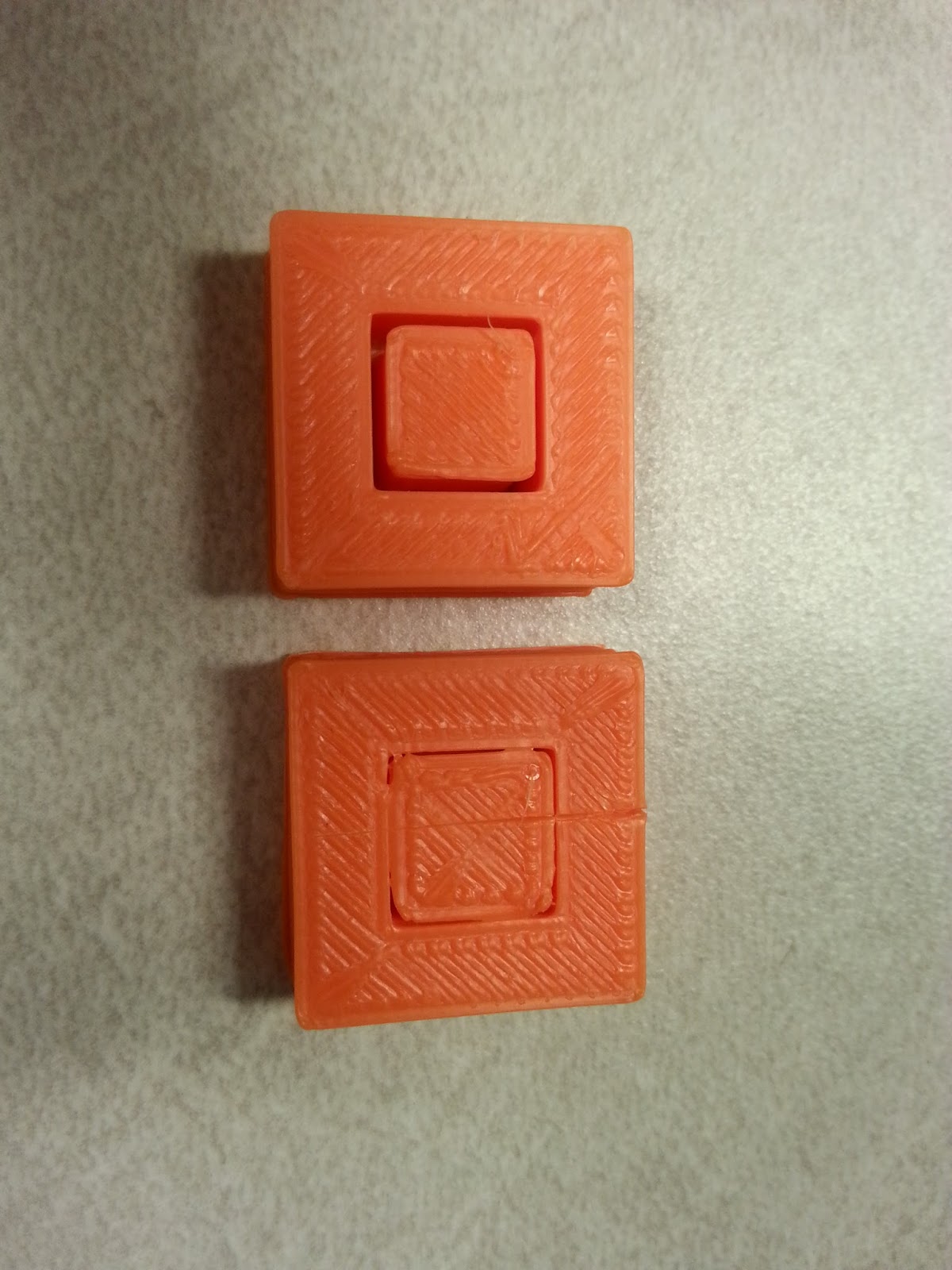
The cubes on the left have a difference of .5 mm between the outer wall of the small cube and the inner wall of the cube it is nested in. As you can probably tell, these cubes are fused together. The cube on the right has a gap of 1 mm and the cubes are not at all fused together.
We have found that a 1 mm gap has been a safe number when building these sorts of objects, but it is not always easy to ensure this throughout the entire part. When you are making your first print of an object with these sort of interlocking parts, it’s always best to give it as much room as possible while still keeping the design function.
2. Give special consideration for holes in round fitted parts.
STL files, the type of file that any 3D printer uses to build objects, consist entirely of triangles that make up the geometry of your object. When design software is trying make a circle, in our case the kind that would be in a round fitted part, then it has to do so with triangles. As you can imagine, it has to make some compromises. When the design software makes these compromises, especially in the case of round holes, it will always choose the circle to be smaller rather than larger, as holes are easier to drill out, rather than made smaller.
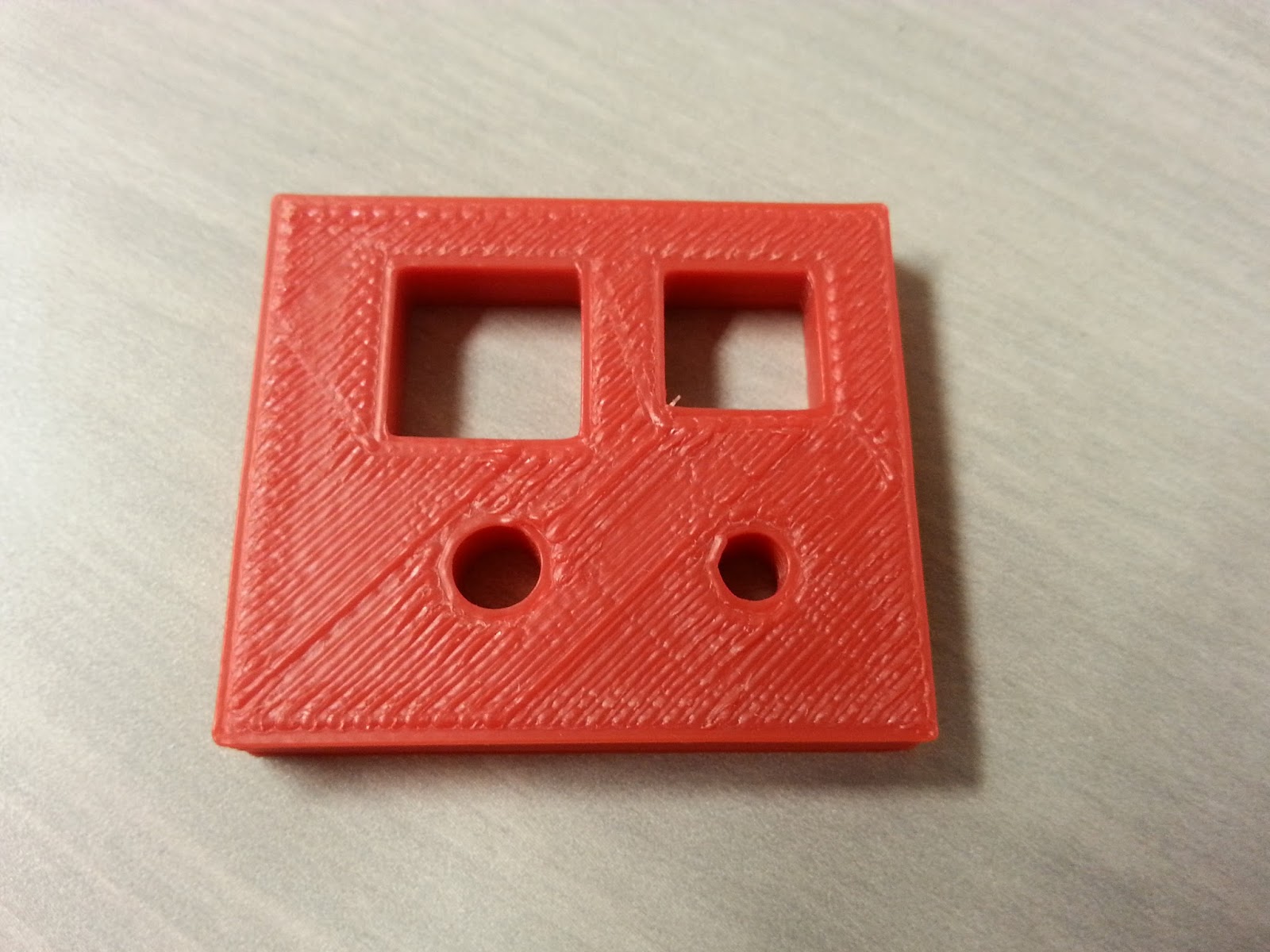
Here is an example of a hole that has been designed without this factor in mind. The smaller hole has been designed for a 3/16 inch dowel to be inserted. As you might guess, the hole that has been printed is much too small for this to happen.
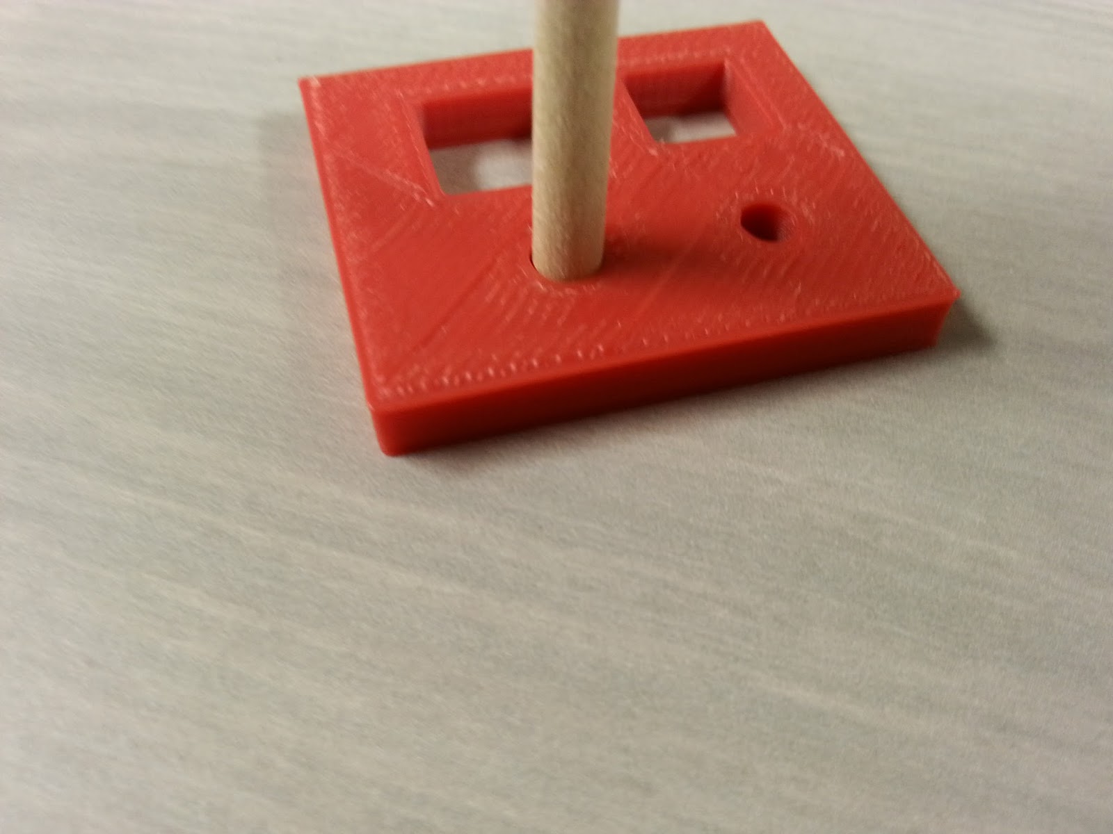
The hole on the left is scaled by a factor of 1.2 and fits the dowel perfectly. Unfortunately this number can’t be used as a rule of thumb for any hole, or even any printer from that matter. To make a long story short, between printer software, printer calibrations, and the various tools that are involved, your best bet is to make a few test prints that have the fitting that you want to make, and adjust your design as you find necessary.
3. Reduce Flow rate to improve spacing between parts.
In general, the software that will run your print has a good idea of how much plastic needs to be extruded from its nozzle to produce an object close to your specifications. As shown in the previous tips, this amount may be more than your design had specified, making the fitted pieces in your objects fuze together or not fit at all. In addition to the methods above, you can change the flow of plastic for the entirety of the print. In many cases this fixes some or all of the problems detailed above, without having to change your design. This is especially useful when you have downloaded a design that someone else has made and you are not familiar with design software.
This method of course has its limitations. Often, although the interlocking parts of your object now fit together, other parts of your object now no longer have the right amount of plastic fill. This can appear as features being under-defined, or top layers showing holes.
by Corbett Larsen, Student Assistant for the Web and Emerging Technologies Unit at Albertsons Library
No comments:
Post a Comment